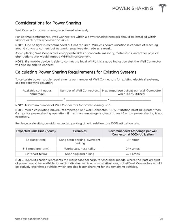
POWER SHARING Considerations for Power Sharing Wall Connector power sharing is achieved wirelessly. For optimal performance, Wall Connectors within a power sharing network should be installed within view of each other whenever possible. NOTE: Line of sight is recommended but not required. Wireless communication is capable of reaching around concrete corners but network range may degrade as a result. Avoid placing Wall Connectors on opposite sides of concrete, masonry, metal studs, and other physical obstructions that would impede Wi-Fi signal strength. NOTE: If a mobile device is able to connect to local Wi-Fi, it is a good indication that the Wall Connector will also be able to connect. Calculating Power Sharing Requirements for Existing Systems To calculate power supply requirements per number of Wall Connectors for existing electrical systems, use the following equation: Available continuous Number of Wall Connectors: Max amperage output per Wall Connector amperage: when 100% utilized: _____________________ ÷ ________________________ = ________________________ NOTE: Maximum number of Wall Connectors for power sharing is 16. NOTE: When calculating maximum amperage per Wall Connector, 100% utilization must be greater than 6 amps for power sharing operation. If maximum amperage is greater than 48 amps, power sharing is not necessary. For large scale sites, consider expected parking time in relation to a 100% utilization rate. Expected Park Time (hours) Examples Recommended Amperage per wall Connector at 100% Utilization 6+ (long term) Long term parking, overnight 12+ amps parking 3-5 (medium term) Workplace, hospitality 24+ amps 1-2 (short term) Shopping and dining 32+ amps NOTE: 100% utilization represents the worst case scenario for charging speeds, where the least amount of power would be available for each individual vehicle. In most situations, not all Wall Connectors would be actively charging a vehicle, which enables faster charging for the remaining vehicles. Gen 3 Wall Connector Manual 25
 Tesla Gen 3 Wall Connector | Installation Manual Page 26 Page 28